Most problems with ESDI hardware result from wrong cabling and defect cables. This chapter is short and important.
You need two ribbon cables to connect one ESDI drive to the controller card, a 36pin cable and a 20pin cable. For a second drive you need an additional 20pin cable. The 36pin cable transfers the control commands for up to seven but usually two ESDI devices. The 20pin cable transfers the data stream to and from one single ESDI device.
First inspect the cable for broken wires or missing isolation and the plugs for bent pins.
Connect the cables to the controller before you plug the card into a free slot. Make sure to connect pin one of the cable plug to pin one of the drive's/controller's ESDI interface connector. Pin one of the cable plug is marked with a small arrow symbol on the plug and/or a colored wire at the cable. Pin one of the ESDI interface connector on the controller card is specified by a printed '1' or by the connector's canted white edge or by a square solder pad.
The ESDI drive interface use keyed edge cart connectors. Look
for edge card connectors with a strip. They prevent wrong way connections.
IBM PS/2 computer use keyed edge card connectors at the controller side of
the ESDI interface as well. This simplifies the cable setup a lot.
If you have no keyed edge card connectors, inspect the drive's printed
circuit board for any of the above mentioned marks. In general, pin one
of the drive's pcb points towards the power connector. Alas, this is not
invariably the case. With Hewlett Packard's 97548E drive it's the other
way round.
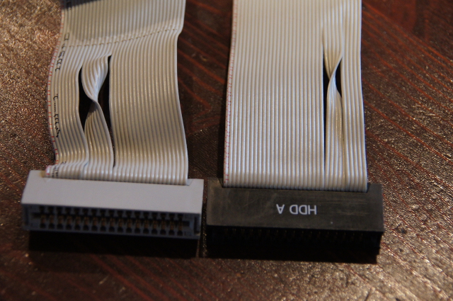
If you use a twisted cable, do not confuse the hard drive control cable with a floppy drive control cable.
The picture shows left hand the floppy drive control cable with a broader twist more close to pin 1 and right hand the hard drive control cable with a smaller twist more close to pin 34.
Do not connect ST506/412 MFM or RLL devices to ESDI devices or vice versa.
Be warned: Using defect or wrong cables, wrong way connections or incompatible devices may damage the controller card, the drive or both.
After cabling is done, the system, the controller and the disk drive have to prepared to work together. Go on to the ESDI controller's manufacturer setup.
Table of Content
| © 2016 Wolfgang Gehl |
|