Sytem BIOS Setup
If the ESDI controller uses default settings,
(hard disk controller and controller BIOS enabled;
primary hard disk port address 1F0-1F7;
IRQ 14 for hard disk access;
BIOS address = C800)
enter drive type 1 in system BIOS for the first drive
and, if a second drive is installed, use drive type 1
for the second drive too. Don't worry about the
wrong drive type, the controller will make the correct
values available to the system at boot time. Do not use
other drive types.
A low-level format is the basic handshake between
controller card and hard drive. It is performed by a
technician when setting up the system and almost never
by the end user. Without this handshake, you cannot
place an operating system or other data on the hard disk.
Each controller card uses a specific format that allows
a low-formatted hard disk to be swapped between controller
cards from the same manufacturer, but unfortunately
there are exceptions. Therefore, replacing the controller
card regularly means that the hard disk must be given
a new low-level format.
In case the system is able to cache the ROM
BIOS area, where the ESDI controller BIOS resides, turn
off the cache, at least for the installation process.
After Installation you may try to cache the controller
BIOS.
Manufacturer Specific Setup
For the setup discussion it makes sense to sort the controllers
by manufacturer, cause every manufacturer uses a similar setup
procedure within his controller family.
Screen prints are made with the freeware Screen Thief 2.01
for DOS, which can be found in the utility section of the
Gibson Research web site
here
or google for 'st201f.zip'.
|
|
|
|
|
Adaptec produced ESDI controller cards for the ISA bus,
the MCA bus, and ESDI bridge controller cards for the SCSI
bus. With the emerging of native SCSI and IDE hard drives,
they dropped the Controller Board (ACB) product line
and focused on SCSI with their Host Adapters (AHA) product line.
The ESDI development reached 20MHz data rate. There are no
24MHz ESDI controller cards from Adaptec, at least no one I
know of.
The tested controller cards are later exponents of Adaptec's ESDI family. The ACB-2322B is a 10MHz card with 8KB track cache. With Board Revision C it will support 15MHz drives. It's possible to format hard- and soft-sectored drives. The user is able to create a single DOS partition up to 528MB with 63-sectors-per-track translation mode enabled. With 8KB track cache the controller will read ahead 16 sectors from a track. That is enough to support 1-1 interleave but not enough to cache a whole track, since a 10MHz drive has 34 to 36 sectors per track.
The ACB-2322D is the last ESDI controller card from
Adaptec. The manufacturer says it supports 20MHz drives
(my ACB-2322D does 23MHz as well) and 1-1 interleave. It
is able to store 64KB or 128 sectors in its read ahead cache,
making it a very fast controller card.
Again, a single DOS partition up to 528MB may be created
with 63-sectors-per-track translation mode enabled. If the
drive has a higher storage capacity the ACB-2322D can split
the drive in two logical drives. With drive splitting in use,
both logical drive stay within the DOS geometry boundarys.
Now it's possible to address over 1GB of storage space with one
physical and two logical drives under DOS. Alas,
if a second physical hard drive is connected to the
ACB-2322D the drive splitting mechanism won't function
any more. So the storage limit for DOS with the ACB-2322D
is round about 1GB either way.
Adaptec offers a thorough verify after low-level- format with it's nefmt.exe utility. Thorough verify is mandatory for a production system. For thorough verify with the big 15MHz and 20MHz drives, calculate at least 12 hours. For a standard verify after low-level-format use the fdformat.exe utility.
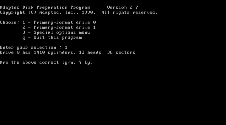
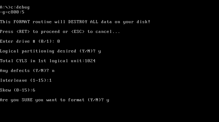
If you don't like the DOS utilities, it' possible to
do the drive preparation in the usual manner with
ACB-2322B-8 and ACB-2322D. At the DOS debug prompt, the
user opens the Controller BIOS with
g=c800:5
(In case an other BIOS address is used, e.g. D800,
enter it here instead of C800.)
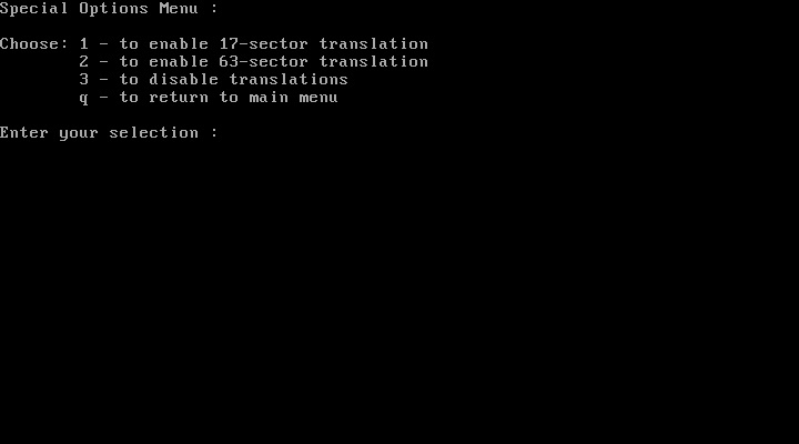
With the controller BIOS the low-level-format, as well as
defect management and drive geometry translation is done.
(You may click the images to magnify.)
Reboot the system after the low-level format and fdisk and format the drive.
If the drive should be splitted in two logical drives, a Jumper has to be installed at the J7-2 location of ACB-2322D before the drive is low level formatted.
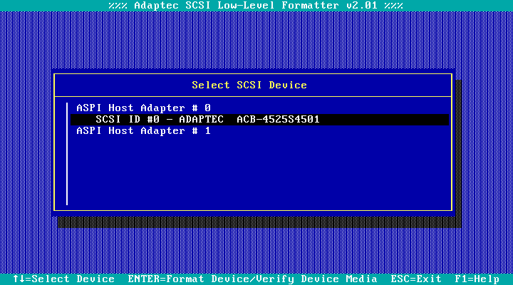
The ACB-4525 S4501 connects an ESDI drive to an 8Bit
narrow SCSI bus. The first SCSI drives were often ESDI
drives with a bridge controller drive card like the ACB-4525.
Since the ACB-4525 is a SCSI device, a SCSI host adapter
is needed. Low-level-format is made with an AHA-2742AT
from Adaptec, loaded DOS ASPI driver at boot time, and the
scsifmt.exe DOS-utility.
All needed software
is part of Adaptec's EZSCSI software package.
The ACB2525 uses defect mapping by default and leaves you
with an error free drive after low-level-format. The defect
management and interleave setting is handled by the bridge
controller card without user intervention.
The storage addressing is now a task of the SCSI host
adapter.
Compaq integrated ESDI storage in their high end server and desktop systems e.g. the Deskpro 386 and 486 models. The controller cards were original Western Digital cards, like the WD1005-WAH, or customized variants of the WD1007 and WD1009 cards. The customized variants write a format incompatible to the Western Digital cards. Like the WD1007V the Compaq 15MHz ESDI controller supports hard sectored drives. Perhaps the Compaq 15MHz controller supports 36 sectors per track with a one-by-one interleave too, but I have tested with 35 sectors per track only.
There is no BIOS chip on the Compaq cards. The drive setup process is done from within the system setup. Compaq PCs use reference disks or the reference partition for system setup. For that reason the low-level-format should be done from within a suitable Compaq machine.
Unfortunately I have no Deskpro but I was curious to see,
how well the Compaq ESDI Controller would perform. So I was stupid
enough to low-level-format an ESDI drive with the DiskManager software
form Ontrack, which is perfect for ST506/412 MFM or RLL,
but fatal for ESDI. The primary defect list or bad track list was
deleted from the drive. In turn a deleted primary defect
list makes a drive unusable for other ESDI controller cards.
They just refused to see the drive at all, even if the drive and
cabling setup is correct.
The last and the last but 9 cylinder, which holds a copy of the
bad track list, are protected during regular setup, but both will be
overwritten with partitioning software like DiskManager
or SpeedStor, if they are used for low-level-formatting instead of the controller
BIOS. Be warned: curiosity may kill a drive.
Apart from this a Compaq ESDI controller will operate in a standard PC, but outside a Compaq it will not support defect management or track-mapping-translation mode.
The Compaq 15MHz ESDI controller seems to be a modified WD1007V-SE1 with a 15MHz Intel 80186 processor instead of the 10MHz 80186 on the WD1007V. This makes the Compaq card slightly faster than the WD1007V.
CompuAdd was one of the biggest seller of PC systems and PC equipment in the US up to 1993, when the company went bankrupt. They developed own add on cards like the HardCache/ESDI controller card in 1989. As a cache controller card it was considered to be one of the most fast mass storage controller cards available at that time.
Since the company vanished in 1993 it was hopeless to find the software utilities necessary to operate the controller card. But in May 2016 someone 'bit by the retro bug' found the utilities on the hard disk of an huge old 286 PC with a HardCache/ESDI controller inside. He was kind enough to safe this piece of software and made it available to the public. Thanks again to dogchainx!
With this software, it is possible to low-level format an ESDI drive. Alas, there is currently no user manual available. For that reason it is not clear, whether the controller card operates in soft sector mode and which data rates and which sector counts it supports. In the test environment the controller card operates well in hard sector mode with 36 sectors per track for 10MHz drives and 53 sectors per track with 15MHz drives.
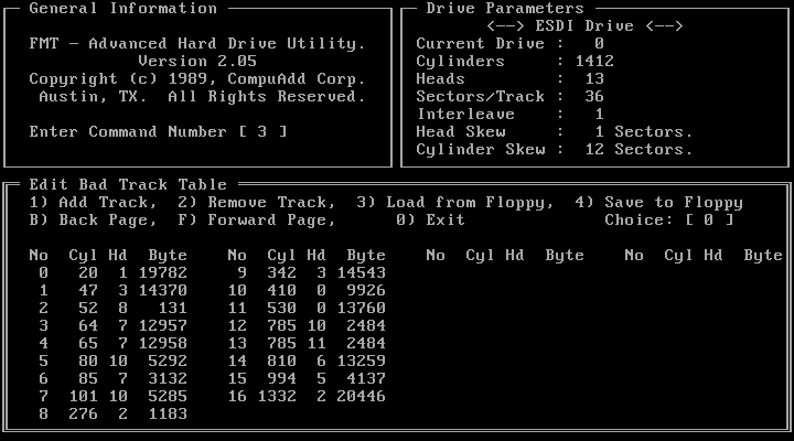
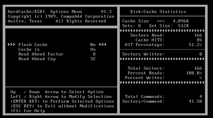
The HardCache Utilities consist of the "FMT - Advanced Hard Drive Utility" (fmt.exe) and the "HardCache Options Menu" (hcu.exe). fmt.exe will low-level-format the drive. hcu.exe allows for fine tuning the cache parameters. fmt.exe offers estimated values for head and cylinder skew which should be raised a little to avoid unnecessary disk revolutions and increase data throughput.
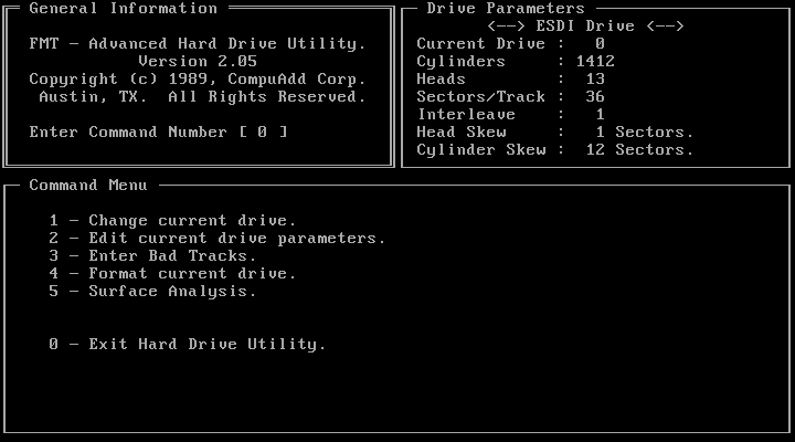
Moreover it's possible to change the physical drive parameters (cylinders, heads, and sectors per track). Since ESDI drives autoreport their geometry, this feature should be used with care. The interleave factor should be 1 except the controller card resides in a 286 not fast enough to handle the HardCache's data throughput.
fmt.exe reads the bad track list from the drive. There seems to be no option for spare sectors (at least I could not find them).
With the help of hcu.exe it is possible to manipulate the cache parameters or to turn off the cache.
The HardCache/ESDI controller card operates in 63-sector-translation mode by default. There seems to be no other translation mode available. This means, the addressable storage space under DOS maxes out at 528,482,304 byte. Storage space above this limit is still available to Unix-like operating systems or Novell NetWare, which are not affected by the 1024 cylinder limit.
Data Technology is a name that hardly anyone knows today. In the late 1980s it was one of the largest hard disk controller manufacturers. DTC produced ESDI controllers for the ISA and EISA bus.
I will test relative late controller cards. The DTC 6280-15T and
the DTC 6282-15Z are 15 MHz ISA cards. The DTC 6282-24 is a 24MHz ISA
card. The EISA cards, DTC 6290 and DTC 6295 are both 24MHz cards.
The DTC 6282-15Z and the DTC 6290 don't have an own BIOS.
Use hard sectored drives with DTC controllers. A sector count of 36 for
10MHz and 54 for 15MHz drives is possible. For drive setup the DOS
utility 2bdfmt.exe is recommended, since it calculates the head- and
cylinder-skew values, while some of the old controller BIOSs don't.
Instead, those BIOSs expect user input for head- and cylinder-skew.
Additionally 2bdfmt.exe will format drives, which the controller
BIOS may refuse to detect.
If you don't like the DOS utilities, drive preparation is
possible in the usual manner. At the DOS
debug prompt, the user opens the Controller BIOS with
g=c800:5
(In case an other BIOS address is used, e.g. D800,
enter it here instead of C800.)
With the controller BIOS the low-level-format, as well as defect management
and drive geometry translation is done.
Reboot the system after the low-level format and fdisk and format the drive.
The DTC 6282-24 is the latest ESDI controller card I own. It's BIOS is dated from 1991 and offers a graphical drive setup. (You may click the images to magnify.)

In contrast to the other controller cards the DTC 6282-24 employs VRAM instead of SRAM for track caching.
The EISA cards are caching controllers with 2MB and 4MB RAM maximum. They operate in ISA WD1003-compatibility mode, unless the EISA device driver is loaded.
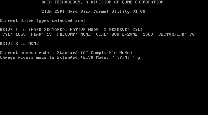
The DTC6295-24 enables 32-Bit EISA mode through the card BIOS. Together with an operating system specific software device driver both EISA cards perform with outrageous high data transfer rates.
As already mentioned, 2bdfmt.exe may be used for drive setup too. Apart from that, there is a nice additional feature. Generally low- level-formatters give the opportunity to the user to enter defects manually in the grown defects list (or secondary defect list).
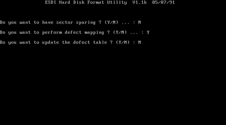
When 2bdfmt prompts you to alter the defect list, like in the picture above, you are able to edit the primary or manufacturer defect list. If the primary defect list has been overwritten erratically this may be the only way to make a defunct drive live again.
Distributed Processing Technology (DPT)
DPT was well known for it's high end SCSI host adapters. At the end of the 1980s they produce a caching disk controller for the ESDI interface, the PM3011E/75.
The PM3011E is a disk coprocessor board. A Motorola 68000 processor manages the ESDI storage hardware with 512KB RAM standard, upgradeable to 16MB RAM. Setup is done from within DOS with the dptfmt.exe utility. It was considered one of the most fast controller cards of it's time. The retail price for this device was well above 1K USD in 1990.
Use hard sectored drives up to 20MHz drives with the PM3011/E75.
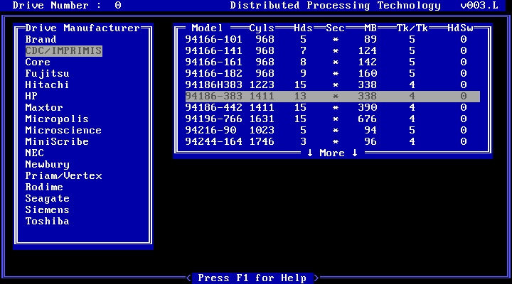
The PM3011/E75 is a universal translator, which means it will use
any combination of cylinder, head, and sector per track values as
long as they do not exceed 1024cyl, 16hd, and 63spt. It's possible to
enter these values in the user defined drive type in the system BIOS.
You may enter the usual drive type '1' in the system BIOS too, if the
BE3011 BIOS table expander chip should make the geometry translation.
The BE3011 (BT-0001-002-H) fortunately supports head mapping for
drives with more than 504MB storage space even though the manual says
it doesn't. Place a jumper on Y7 to activate the BE3011.
At boot time the BE3011 performs controller diagnostics which
may be interrupted by pressing any key.
It takes a while until the boot process continues. Get a coffee. Wait.
At the DOS prompt enter dptfmt. This will start the drive preparation
utility from DPT. Dptfmt will recognize the ESDI drive automatically
and low-level-format the drive.
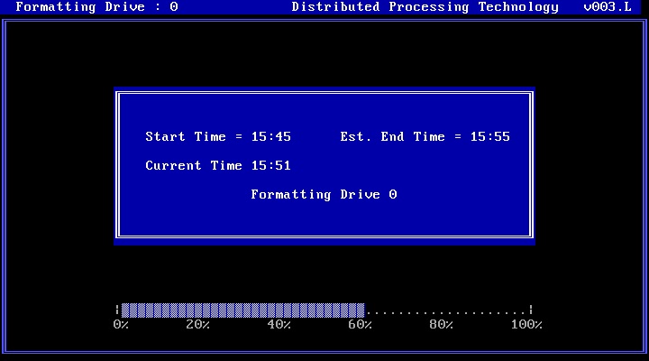
Spare sectoring is used as default. Spare sectoring
reduces the sector per track count by 1 or more sectors. Spare sectors
are used to map sectors, which are located in defect areas, leaving
the user with an error free drive.
Last step is to calculate the emulated disk geometry for the system
drive table (or user defined drive type if available) or to choose
one of the BE3011 drive types.
Reboot the system after the low-level format and fdisk and format the drive.
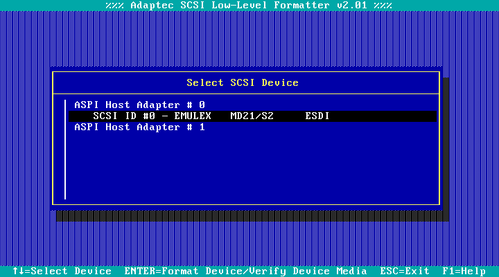
Emulex produced a series of SCSI to ESDI bridge adapter cards
of which the MD21 is tested here. Just like the Adaptec ACB-4525,
the MD21 needs a SCSI host adapter and software for the drive
setup. Usually SCSI storage is not signed in the system BIOS. So
if there is a hard disk connected to a SCSI adapter only, the system
BIOS hard drive type is '0' or 'not installed'. The storage space
addressing is a task of the SCSI host adapter.
Low-level-format was made with an AHA-2742AT
from Adaptec, loaded DOS ASPI driver at boot time, and the
scsifmt.exe DOS-utility.
All needed software
is part of Adaptec's EZSCSI software package.
The MD21 uses defect mapping by default and leaves you
with an error free drive after low-level-format. The defect
management and interleave setting is handled by the bridge
controller card without user intervention.
Use hard sectored 10MHz and 15MHz drives adjusted to 36 and 54 sectors per track, respectively.
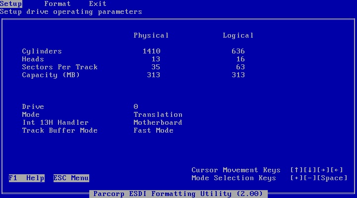
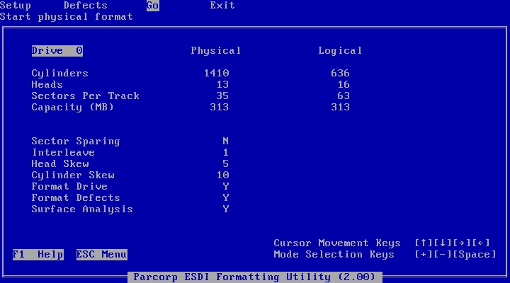
The EV-348 controller card is based on a cirrus logic chip. It operates up to 20MHz drives and has a 32KB SRAM track buffer. This controller requires hard sectored drives with a sector count of 35 or less for 10MHz drives and a sector count of 53 or less for 15MHz drives. If the sector per track value is to high, the controller BIOS will not start. 20MHz drives are not affected from this behaviour.
Setup is done in the usual manner. At the DOS
debug prompt, the user opens the Controller BIOS with
g=c800:5
or
g=c800:6
(In case an other BIOS address is used, e.g. D800,
enter it instead of C800.)
Unfortunately I couldn't find any rule for choosing the right BIOS starting point. Sometimes it works with c800:5 sometimes with c800:6. If you finally manage to open the BIOS you will be greeted by Pacorp, the BIOS manufacturer. At first you have to choose a proper drive geometry translation mode. After a reboot the BIOS offers a low-level-format with media verify, and the defect management. (You may click the images to magnify.)
Reboot the system after the low-level format and fdisk and format the drive.
International Business Machines (IBM)
While the industry standard defines a disk-controller-to-drive interface, with IBM, ESDI means additionally a direct bus-attachment interface that provides disk storage with:
- more than 17 data sectors per track,
- error-free storage trough defect management and spare sectors,
- storage space up to 1GB per drive trough a 64 head 32 sectors per
track head mapping mode.
Thus IBM designated the 'Fixed Disk Drives' from the PS/2 models 50, 50Z, 70 and P70 as ESDI drives and their 72-pin connector as DBA (Direct Bus Attached) ESDI.
The controllers and drive combinations corresponding to the ESDI industry standard can be found in the PS/2 models 60 and 80. However, IBM decided to go its own way with defect management. This led to compatibility problems between ESDI hardware from IBM and ESDI hardware from other manufacturers. During the lowlevel format, the IBM ESDI controller overwrites the defect map on a non-IBM hard disk and the non-IBM controller causes the same disaster on an IBM hard disk. With a lot of effort you have to manually enter the list of defective areas during the lowlevel format procedure - if the manufacturer provides this list at all.
Head mapping is standard for IBM ESDI systems. The big advantage is that neither the system installer nor the user has to worry about addressing disk space over 504 MB since the IBM head mapping scheme allows 1GB storage address space. Unfortunately, there are two annoying disadvantages. Access times increase because the position of a physical sector is calculated with an algorithm located in the ROM of the ESDI controller and the read-ahead cache of the controller, normally 64 sectors, is disabled. ESDI storage from IBM in microchannel systems is therefore significantly slower than comparable 10Mhz ESDI hardware in AT bus systems.
Micro channel systems compatible with ESDI storage support up to
2 hard disks under system BIOS control. Allowed are exclusive
- 2 disks connected to 1 ESDI controller,
- 2 disks connected to 1 ST506 (MFM or RLL) controller,
- 1 disk connected to an ESDI and a ST506 controller each (2 total).
The ESDI drive with ID1 on a non-twisted 34pin cable or the ESDI
drive with ID2 at the end of a twisted 34pin cable is the boot
device in all of the above cases.
The micro channel ESDI controller is configured through the
reference disk. No jumpers have to be placed on the controller card.
Low-level-format routines are available through pressing "crtl"+"a"
while in the setup menu of the reference disk. This procedure works
with IBM certified hard drives only.
To low-level-format other manufacturer's hard disks the file
llformat.exe on the reference disk may be patched in a way as
it is described
here.
Be warned: the patched llformat.exe will overwrite the primary or
manufacturer's defect list. You will not be able to
setup this drive together with an other controller card after.
I prefer a Novell utility called "fmtps2" which is available
here. In contrast to the technical information, it will
low-level-format any 10MHz ESDI drive with the IBM ESDI
Fixed Disk Controller. The "fmtps2" utility will not verify the
platter surfaces for defects. For that reason defect areas may
occur, when an operating system format is processed.
The reference disk utility "llformat.exe" use defect mapping by default and leaves you with an error free drive after low-level format. Defect management and interleave setting is handled without user intervention.
The IBM ESDI Fixed Disk Controller operates 10MHz hard sectored drives, adjusted to 36 sectors per track.
Reboot the system after the low-level format and fdisk and format the drive.
The NCL 5355 is a 10MHz controller card with 32KB SRAM track buffer. It operates hard sectored drives up to 36 sectors per track.
Drive preparation is made in the usual manner. At the DOS
debug prompt, the user opens the Controller BIOS with
g=c800:5
With the controller BIOS the low-level-format, as well as defect
management and drive geometry translation is done.
Reboot the system after the low-level format and fdisk and format the drive.
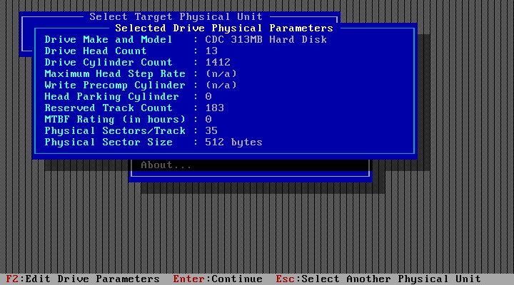
The hyperSTORE 1600 is a caching disk controller with up to 64 KB SRAM track buffer and up to 16MB cache RAM. For 10MHz and 15MHz drives it will low-level-format in soft sector mode to 35spt, respectively 52spt, regardless of the drive setup. 20MHz drives are low-level formatted in hard sector mode. All setup is done with the hs.exe utility. (You may click the images to magnify.)
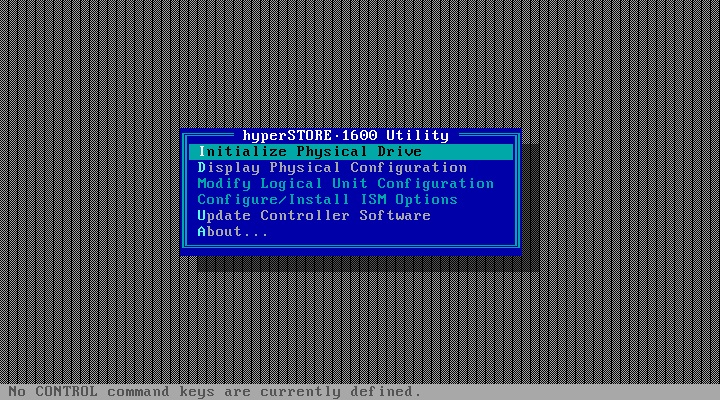
During install the system BIOS drive type should be set to '0' or 'not
installed'. Disable any hyperSTORE DOS driver in config.sys. Start hs.exe
and low-level-format the drive using defaults. Now you have to configure
at least one logical volume for the drive. This could be a tricky task,
cause the hyperSTRORE doesn't support sector translation. All geometry
emulation has to be done by raising the head count up to 16 in WD1003
mode and up to 64 in 'SPP Block Transfer Mode', which is the first choice
for maximum performance in a DOS environment.
If, for whatever reason, you are stuck to WD1003 mode, storage addressing
is limited to 1024 cylinders, 16 heads, and the physical sectors per track
count. After reboot the drive has to be logged in the system BIOS as
drive type '1'.
If you decide for SSP Mode choose 'SPP Geometry Translation' for drives
with more than 1024 cylinder. (Press "Ctrl"+"T" when in "Logical Volume"
menu.) Now storage addressing is limited to 1024 cylinders, 64 heads, and
the physical sectors per track count. Accept the default setup for the
logical drive geometry and leave the drive type in the system BIOS as
'not installed'. In SSP mode software drivers for operating systems other
than DOS are required.
In the last step you choose the host interface mode. The relevant ones are
'SSP Block Mode' and 'Western Digital WD1003 Compatibility Mode' as
already mentioned. Exit the hs.exe utility and reboot. If necessary change
the drive type values in the system setup, fdisk, and format the drive.
If your drive has more than 63 physical sectors per track, like some 20MHz drives, DOS sees only 63 sectors, cause there is no sector translation with the hyperSTORE controller. For the DK515 drive this leads to a 8% storage cut. Furthermore the logical volume geometry has to be adjusted by decreasing the amount of logical storage space until it reflects the drive's storage space, as if it would have 63 physical sectors per track only.
Spare sectoring is used as default. Spare sectoring reduces the sector per track count by 1 or more sectors. Spare sectors are used to map sectors, which are located in defect areas, leaving the user with an error free drive.
20MHz drives produce a cooling problem with the hyperSTORE. I had to use an additional fan to blow air just between the board and the media adapter. Without this fan, the hyperSTORE produced numerous write errors while formatting the drive.
The hyperSTORE is an impressive and innovative controller card. Common storage interfaces, like ST506, ESDI, IDE, and SCSI may be used together at a time through media adapters, which plug into the controller board. Cache RAM may be expanded with standard SIMM RAM. Performance restrictions of the WD1003 hard disk standard could be overcome with the block transfer mode the card offers.
Reboot the system after the low-level format and fdisk and format the drive.
Scientific Micro Systems (SMS)
There are at least two different official jumper definitions for the OMTI 8620 controller card. At the end configuration of this card comes down to trial and error.
To tell a long story short: on my OMTI 8620 board (two EPROM
1002661-E and 1002577-E) W4, W5, W6, W7, W8, W22 and W23 have
to be jumpered. This configuration means, that:
- up to two ESDI drives and no ST412/MFM drive may be connected,
- the floppy controller owns the standard system floppy drive port
(if an other floppy drive controller is present, it has to be
disabled or set to an alternate port).
- the BIOS address is C800H
- maximum I/O performance is adjusted.
Furthermore the OMTI 8620 BIOS should be cached after low-level-
format.
Apart from the configuration woes it's a remarkable hard disk controller, because it's able to operate one ESDI and one MFM hard disk at a time. I don't know of an other card with that feature.
Additionally it's per design capable to operate independently from further system hard disks whether ST506/412, IDE or SCSI. You may stuff an OMTI 8620/ESDI combo into a system which already has a e.g. standard AT-controller/IDE combo installed.
Consequently drives connected to the OMTI 8620 must not be installed in the system BIOS. If a drive is connected to the OMTI 8620 and the only drive in the system, the system's drive types are "Not installed" both. In that case the system boots from the OMTI 8620. Whether it's possible to boot anything but DOS from the OMTI 8620 is an other story.
Low-level-format is done in the usual way from the controller BIOS, which is opened with the DOS debug program and the command
g=C800:6
at the debug prompt. (If you alter the address of the controller BIOS, the command has to be altered accordingly). There are no drive geometry mapping options. The only thing you can do is split a drive with more than 1024 cylinders in two logical drives, in order to access the storage space above the 1024 cylinder boundary. There is no advanced defect management like sector sparing. (You may click the image to magnify.)
As you can see, the user has to know the correct skew value. (Not sure whether head or cylinder-skew, I suppose cylinder-skew.)
The OMTI 8620 does soft sectoring and formats any 10MHz drive to 35 sectors per track regardless of the drive setup.
Reboot the system after the low-level format and fdisk and format the drive.
Like Adaptec and Emulex, SMS produced SCSI to ESDI bridge adapter cards
of which the OMTI 7200 is tested here. (Thanks to Michael Baeuerle, who
lent his card to me for testing.) The OMTI 7200 allows up to two
ESDI or ST506/412 MFM drives and additional up to two 3,5", 5,25", or
8" floppy drives to be connected to a narrow scsi bus. The SCSI host
adapter setup software does the low-level-format. Usually SCSI storage
is not signed in the system BIOS. So if there is a hard disk connected
to a SCSI adapter only, the system BIOS hard drive type is '0' or
'not installed'. The storage space addressing is a task of the SCSI
host adapter.
Low-level-format was made with an AHA-2742AT
from Adaptec, loaded DOS ASPI driver at boot time, and the
scsifmt.exe DOS-utility. All needed software
is part of Adaptec's EZSCSI software package.
The OMTI 7200 maps out defects by default and leaves you
with an error free drive after low-level-format. Defect
management and interleave setting is handled by the bridge
controller card without user intervention.
With OMTI 7200 use hard sectored 10MHz drives adjusted to 36 sectors per track.
Nearly the complete Ultrastor ESDI line of controller cards will be
tested, all ISA ESDI controller cards and all but one (the Ultra 22F)
EISA controller cards.
All card operate in WD1003 compatibility mode. The EISA cards may be
configured in EISA mode with operating dependent software drivers. They
offer outrageous high data transfer rates.
Use hard sectored drives with Ultrastor controllers. A sector count of 36 for
10MHz and 54 for 15MHz drives is possible.
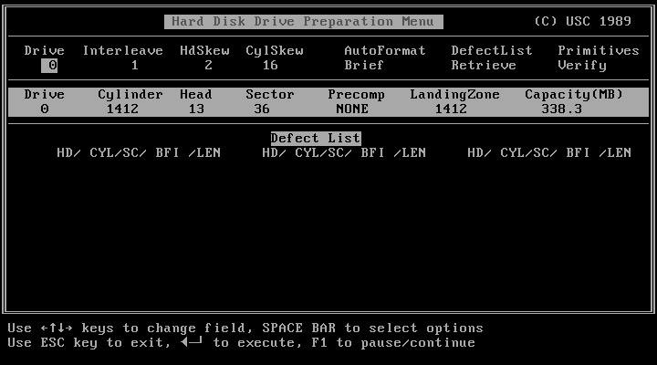
Drive preparation is made in the usual manner. At the DOS
debug prompt, the user opens the Controller BIOS with
g=c800:5
(In case an other BIOS address is used, e.g. D800,
enter it here instead of C800.)
With the controller BIOS the low-level-format, as well as
defect management and drive geometry translation is done.
(You may click the images to magnify.)
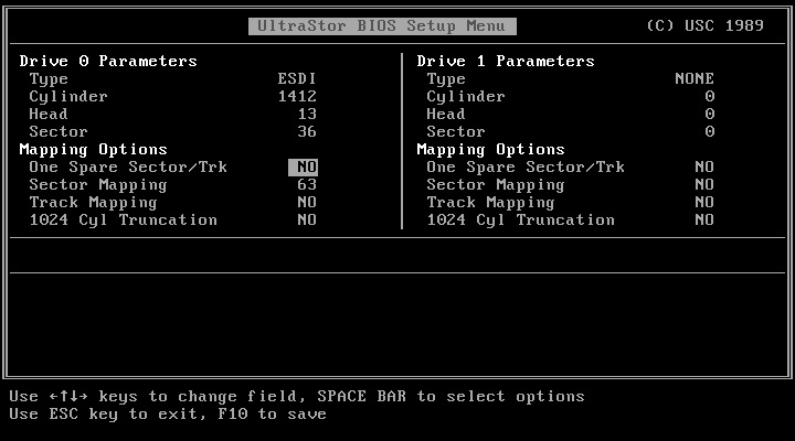
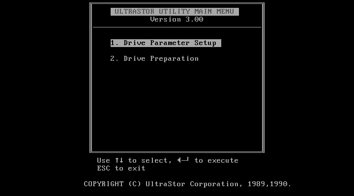
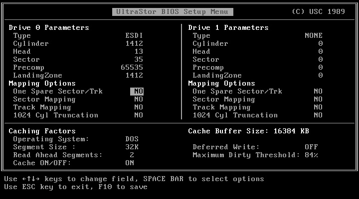
Like the DTC and Everex controller cards, the Ultrastor cards offer a menu driven setup interface, which simplifies the setup process.
Cache controllers, like the Ultra12C, Ultra22C, and Ultra22CA offer cache settings optimized for specific operating systems.
Reboot the system after the low-level format and fdisk and format the drive.
Nearly the complete Western Digital ESDI line of controller cards will be tested, only the WD1007A is missing.
The WD1005-WAH supports two ESDI hard disks. The disks have to be jumpered
for 34 sectors per track hard sector mode only.
As one of the first ESDI controller cards it is compatible to the early
IBM BIOS drive types, which all use a 17-sector-per-track addressing scheme.
Since the WD1005 can address 34 sectors per track, a translation mode is
necessary to avoid the waste of valuable storage space. The 17-sectors-per-
track translation mode lowers the cylinder count under 1024 (which is the
highest cylinder count DOS can address) and increases the head count up to
16 heads max. Now the user can choose a drive type from the system bios,
which reflects but not exceeds the storage capacity of the ESDI drive. The
amount of eventually lost storage space depends on the drive types delivered
by the system BIOS.
The upper storage space limit of the 17-sectors-per-track translation mode
is 142 MB (1024cyl x 16hd x 17spt x 512byte).
Like the standard ST506 controller cards, whether MFM or RLL, the
WD1005-WAH has no on-board BIOS. Instead of using the system BIOS drive type
"1", which the later ESDI controller cards prefer, the user has to choose a
17-sector-per-track drive type which is equal or less to the drive's storage
capacity.
The low-level format has to be done with Western Digital's wdfmt.exe utility.
Wdfmt doesn't detect the physical drive geometry or the cylinder-skew factor
automatically. The user has to know the correct values instead. An interleave
of 2 should be chosen. An interleave of 1 degrades the controller performance
massively.
Alas, wdfmt doesn't seem to low-level-format the drive properly, at least not
in a 486 class machine. As a workaround, the hard disk could be low-level-
formatted by a later Western Digital ESDI controller (e.g. the WD1007). The
controller card has to be configured for 'WD1005 compatibility mode' (which
means hard sector mode). Then the low-level-format can be accomplished by
executing the DOS debug command and starting the BIOS routine (usually
'g=c800:5').
If the hard disk has more than 1024 cylinders AND more than 7 heads AND there
is a user definable drive type in the system BIOS, disable translation mode
by closing jumper W2. In this case enter the physical drive geometry into the
system BIOS.
The WD1005-WAH has no track caching option and supports an interleave of two-
by-one maximum. This means it takes 2 revolutions of the disk's storage platter
for the controller card to read an entire track of data (about 17,5 KB).
The WD1005-WAH is suitable for a 286 or slow 386 PC and for hard disks with
less than 142MB storage space.
The WD1007V-MC1 is a micro channel ESDI controller, which requires hard
sectored drives with 36 sectors per track for the 10MHz drives and 53 sectors
per track for the 15MHz drives. All setup is done with Western Digital's
'll7fmt.exe' utility. 'll7format.exe' does defect mapping by default and leaves
you with an error free drive after low-level format. Defect management and
interleave setting is handled without user intervention.
Do not use IBM ESDI hard drives with WD1007V-MC1 controller card, cause
IBM does not define their drives according to standard ESDI specifications.
The WD1007V-SR2 controller card accepts hard sectored drives with 35 sectors per track for the 10MHz drives and 53 sectors per track for the 15MHz drives. You may force soft sector mode for the 10MHz and 15MHz drives, by placing a jumper at location W1, 9-10.
Drive preparation is made in the usual manner. At the DOS
debug prompt, the user opens the Controller BIOS with
g=c800:5
(In case an other BIOS address is used, e.g. D800,
enter it here instead of C800.)
With the controller BIOS the low-level-format, as well as
defect management and drive geometry translation is done.
The WD1009V-SE2 is the flagship of Western Digitals's ESDI controller line. It offers multi-sector I/O, called 'Block Mode' and additionally a special 'EISA DMA Mode' on computers with 32Bit EISA slots. Below is a picture of the controller card BIOS settings in an EISA PC. (You may click the image to magnify.)
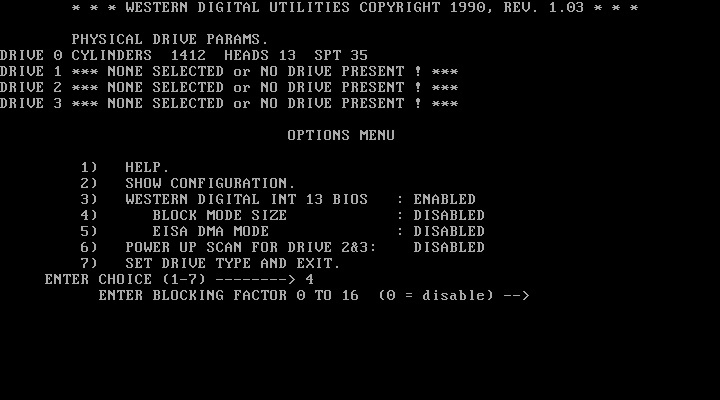
The WD1009V-SE2 isn't an EISA card to be sure, but it can use some EISA configuration features. It never leaves the WD1003 compatibility mode, regardless of the operation mode choosed, which means a very strong device compatibility with standard operating device drivers. Any operating system with standard hard disk driver will work with the WD1009V-SE2.
The WD1009V-SE2 forces 10MHz and 15MHz drives to soft sector mode regardless of the drive's actual setup, which comes to 35 sectors per track and 53 sectors per track, respectively. Forcing the card to accept hard sectored 10MHz or 15MHz drives with a higher sector count by placing a jumper at location W5, 5-6 will degrade performance.
Drive preparation is made in the usual manner. At the DOS
debug prompt, the user opens the Controller BIOS with
g=c800:5
(In case an other BIOS address is used, e.g. D800,
enter it here instead of C800.)
With the controller BIOS the low-level-format, as well as
defect management and drive geometry translation is done.
(You may click the image to magnify.)
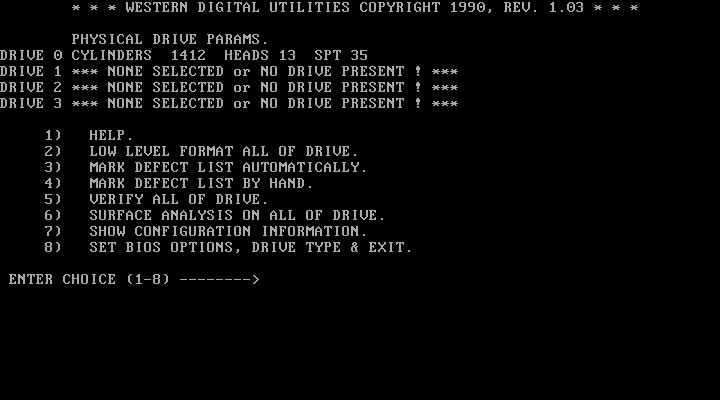
There are some other impressive BIOS options. One of it is the second channel support. Two WD1009V controller cards may co-reside making four hard drives available to the system. The other is the information panel showing the amount of unformatted bytes per track, unformatted bytes per sector, the length of the intersector gap [ISG] in byte, the length of phase locked oscillator [PLO] sync fields, and the head and cylinder skew values.
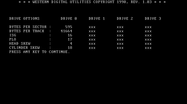
With this information it is possible to setup a drive whose data sheet is lost long ago.
And finally all information at a glance:
Table 10
Controller and Drive Setup Matrix
| Manufacturer | Model | Up to 15MHz Support of: | Default | Optimal Data Throughput at: | Supports: | ||||||||
|---|---|---|---|---|---|---|---|---|---|---|---|---|---|
| Soft | Hard | 10MHz | 10MHz | 10MHz | 15MHz | 15MHz | 15MHz | 20MHz | 22MHz | 24MHz | |||
| Adaptec | ACB-2322B | yes | yes | H/S |
|
| yes |
| yes | | | | |
| Adaptec | ACB-2322D |
| yes | H |
|
| yes |
|
| yes | yes | | |
| Adaptec | ACB-4525 S4501 |
| yes | H |
|
| yes |
|
|
| | | |
| Compaq | 15MHz ESDI Controller | n/a | yes | n/a |
| yes | n/a | n/a | n/a | n/a | | | |
| CompuAdd | HardCache/ESDI | n/a | yes | H |
|
| yes |
| yes |
| | | |
| Data Technology | DTC 6280-15T |
| yes | H |
|
| yes |
|
| yes | | | |
| Data Technology | DTC 6282-15Z |
| yes | H |
|
| yes |
|
| yes | | | |
| Data Technology | DTC 6282-24 |
| yes | H |
|
| yes |
|
| yes | yes | yes | yes |
| Data Technology | DTC 6290-24 |
| yes | H |
|
| yes |
|
| yes | yes | yes | yes |
| Data Technology | DTC 6295-24 |
| yes | H |
|
| yes |
|
| yes | yes | yes | yes |
| Distributed Processing Technology | DPT PM3011E/75 |
| yes | H |
|
| yes |
|
| yes | yes | | |
| Emulex | MD21 | yes | yes | H/S |
|
| yes |
|
| yes | | | |
| Everex | EV-348A |
| yes | H |
| yes |
|
| yes |
| yes | | |
| IBM | IBM ESDI Fixed Disk Controller |
| yes | H |
|
| yes |
|
|
| | | |
| National Computer Ltd. | NCL 5355 |
| yes | H |
|
| yes |
|
|
| | | |
| Perceptive Solutions | HyperSTORE 1600 | yes |
| S |
| yes |
| yes |
|
| yes | | |
| Scientific Micro Systems | Omti 7200 | yes | yes | H/S |
|
| yes |
|
|
| | | |
| Scientific Micro Systems | Omti 8620 | yes |
| S |
| yes |
|
|
|
| | | |
| Ultrastor | Ultra 12C |
| yes | H |
|
| yes |
|
| yes | yes | | |
| Ultrastor | Ultra 12F-24 |
| yes | H |
|
| yes |
|
| yes | yes | yes | yes |
| Ultrastor | Ultra 12F-32 |
| yes | H |
|
| yes |
|
| yes | yes | yes | |
| Ultrastor | Ultra 22C |
| yes | H |
|
| yes |
|
| yes | yes | | |
| Ultrastor | Ultra 22CA |
| yes | H |
|
| yes |
|
| yes | yes | yes | yes |
| Western Digital | WD1005-WAH |
| yes | H | yes |
|
|
|
|
| | | |
| Western Digital | WD1007V-MC1 |
| yes | H |
|
| yes |
| yes |
| | | |
| Western Digital | WD1007V-SE2 | yes | yes | H |
| yes |
|
| yes |
| | | |
| Western Digital | WD1009V-SE2 | yes | yes | S |
| yes |
|
| yes |
| yes | yes | yes |
* H = Controller Hard Sector Mode, S = Controller Soft Sector Mode, and H/S = Drive Hard or Drive Soft Sector mode.
Remember: Controller Mode beats Drive Mode.
** Drive Hard Sector Mode
n/a = not available, not sure or not verified
Now the ESDI storage is ready for use. You might switch to the resources section to find hardware manuals, setup software and some additional links or you jump to the ESDI benchmark section directly.
Table of Content
| © 2016-2023 Wolfgang Gehl |
|