Setup and Benchmarks of Several ESDI Hard Disks and Controller Cards
To setup an ESDI storage system you will configure the drive first,
than configure the controller card, and at last you do the cabling.
Disk Drives and General Drive Setup
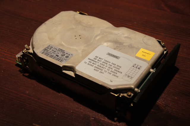
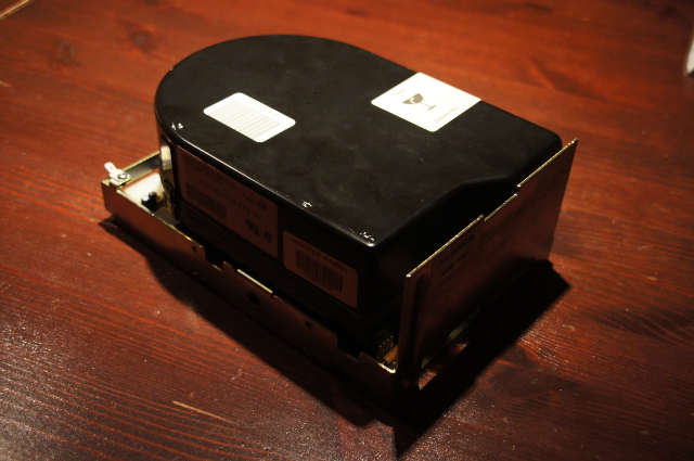
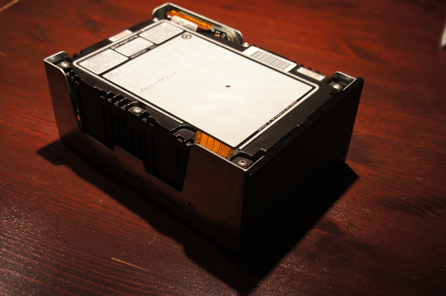
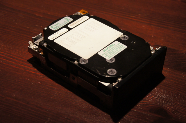
Fifteen drives are available and will be tested. Since the formatted
capacity depends on the controller card used, unformatted capacity is
given.
Let's start with the 10MHz drives ...
Table 1
Tested 10MHz ESDI Drives
| Manufacturer | Model | Form Factor | Unformatted Capacity
(Megabyte) | Click on Picture
to Magnify |
|---|
| NEC | D3661 | 3,5"
half height | 134.5 |  |
| NEC | D5655 | 5,25"
half height | 179.8 |  |
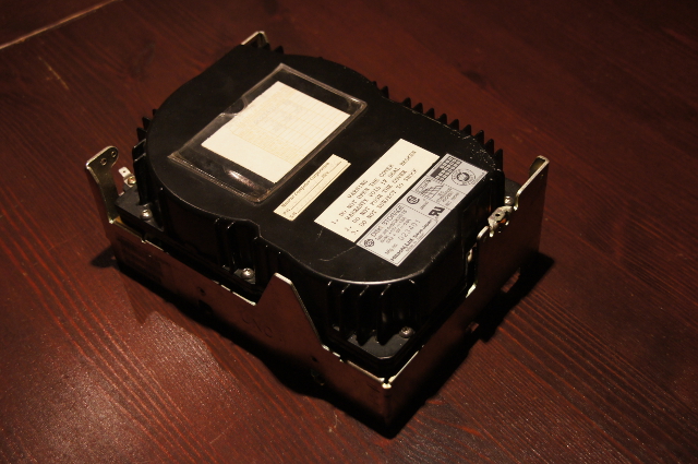
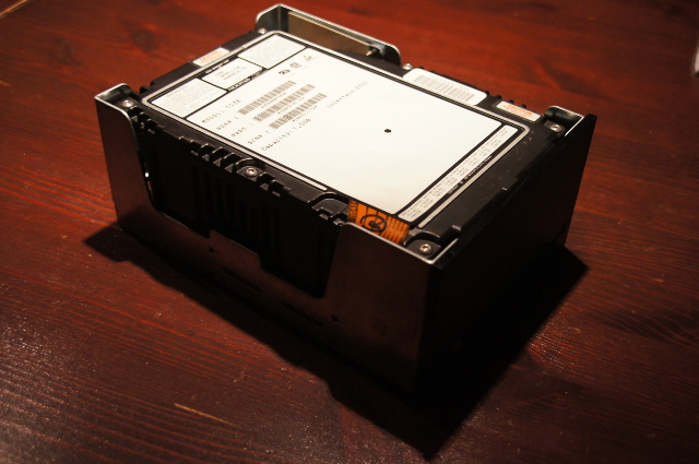
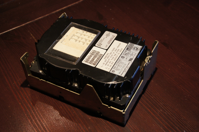
| IBM | 0667-85 | 5,25"
full height | 85 |  |
| Micropolis | 1654 | 5,25"
half height | 178.4 | 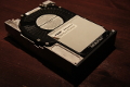 |
| Micropolis | 1558 | 5,25"
full height | 382.3 |  |
| Seagate | ST-1111E | 3,5"
half height | 111 | 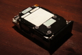 |
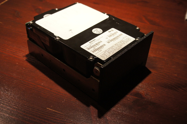
| Imprimis | 94186-383 | 5,25"
full height | 383 |  |
... proceed to the 15MHz drives ...
Table 2
Tested 15MHz ESDI Drives
| Manufacturer | Model | Form Factor | Unformatted Capacity
(Megabyte) | Click on Picture
to Magnify |
|---|
| Micropolis | 1664 | 5,25"
half height | 389.3 | 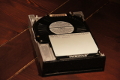 |
| Micropolis | 1568 | 5,25"
full height | 765 | 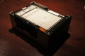 |
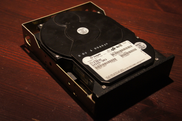
| Seagate | ST-2383E | 5,25"
half height | 383 |  |
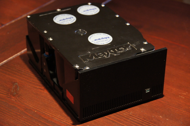
| Maxtor | XT-8760E | 5,25"
full height | 768.9 |  |
... continue with the 20MHz drives ...
Table 3
Tested 20MHz ESDI Drives
| Manufacturer | Model | Form Factor | Unformatted Capacity
(Megabyte) | Click on Picture
to Magnify |
|---|
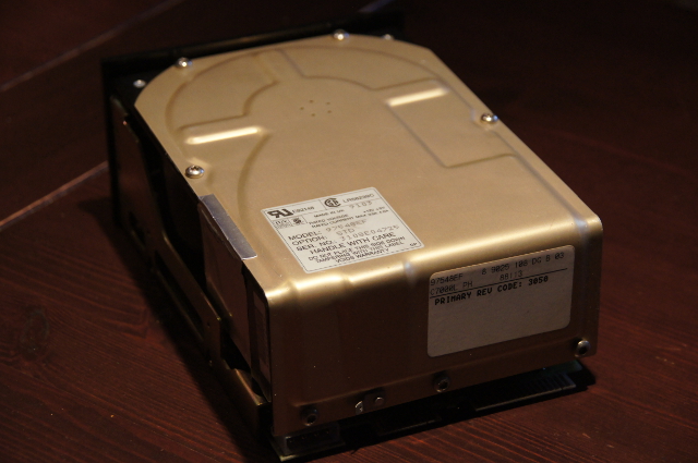
| Hewlett Packard | HP 97548E | 5,25"
full height | 795.9 | 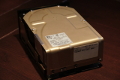 |
| Hitachi | DK515 | 5,25"
full height | 780 | 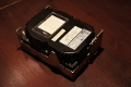 |
... move on to the 23MHz drive ...
Table 4
Tested 23MHz ESDI Drive
| Manufacturer | Model | Form Factor | Unformatted Capacity
(Megabyte) | Click on Picture
to Magnify |
|---|
| Micropolis | 1538 | 5,25"
full height | 1,043 |  |
... and end with the 24MHz drive.
Table 5
Tested 24MHz ESDI Drive
| Manufacturer | Model | Form Factor | Unformatted Capacity
(Megabyte) | Click on Picture
to Magnify |
|---|
| Hitachi | DK516-15 | 5,25"
full height | 1,538 | 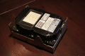 |
ESDI hard drives demand some configuration work,
which is done through jumper blocks or dip switches.
Termination
First of all, the drive at the end of the 34pin control cable
has to terminate the ESDI bus. Usually this is done by
a resistor IC, which is socketed on the drive's printed
circuit board (PCB). All other drives at the
control cable have the resistor IC removed.
Drive Address
Every drive connected at the 34pin control cable needs
a unique drive address. ESDI drives are numbered from 1
to 7. Most controller cards support two drives, very few
four drives. Sometimes the controller manual speaks of
drive 0 and drive 1, which - in case of ESDI - always
means drive 1 and drive 2.
There are 34pin controller cables with a twist between
pin 26 and 28. If you use such a cable, the drive before
and the drive behind the twist should be configured as
drive 2. Now the position of the drive on the 34pin drive
control cable determines the drive address. If the drive
is connected behind the twist at the end of the cable,
it's drive address is 1. If the drive is connected
between the twist and the controller, it's drive address
is 2.
Drive Hard Sectored or Controller Soft Sectored?
Generally drives should be configured for hard sector
mode, with 36 sectors per track (spt) for 10MHz drives
and 54spt for 15MHz drives, thus giving the largest storage
space and the highest data throughput possible.
Some controller cards do not support 36/54spt with an 1-1
interleave. Some of these cards ignore the drive's hard
sector configuration and instead enforce a soft-sectored
low-level-format with 35/53spt. Unfortunately, there are
controller cards, which demand hard sector mode, but will
not function properly or will function with poor performance,
if the user chooses a sectors per track value to high.
Hard drives from 20MHz data rate upwards are hard sector
formatted only.
Miscellaneous Options
The hard disk should be configured for spin up at power on.
Write protection should be disabled.
Last not Least: Grounding of the Disk Drives
All drives but one work when the chassis is grounded to
the drive support structure.
In the IBM PS/2 Model 80 environment the drive's chassis
has to be divided electronically from the support structure.
Use plastic mounting rails for that reason. If the
drive's hard disk assembly (HDA) has a grounding connection
like e.g. the IBM 0667-85 disk drive, use it to ground the
HDA against the support structure.
For the specific drive setup consult the
resources page and look for the drive reference. Do not
change other than the above mentioned drive pcb jumper settings,
if they are in the manufacturer's standard position.
After the drives are jumpered right you might want to have
a look on the
tested ESDI controller cards.
Table of Content
 back to project list
| © 2016 Wolfgang Gehl
 | 
|