Setup and Benchmarks of Several ESDI Hard Disks and Controller Cards
Controller Cards and General Controller Setup
Twenty-seven controller cards are available and will be tested.
For the moment I will divide them in four groups; controller cards
for the Industry Standard Architecture (ISA), cards for
the Extended Industry Standard Architecture (EISA), cards
for the Micro Channel Architecture (MCA), and bridge controller
cards for the Small Computer System Interface (SCSI).
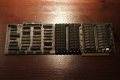
These are the ISA cards...
Table 6
Tested ISA ESDI Controller
| Manufacturer | Model | Supported Data
Rates (MHz/s) | Click on Picture
to Magnify |
|---|
| Adaptec | ACB-2322B | Rev B: 10
Rev C: 10, 15 |  |
| Adaptec | ACB-2322D | 10, 15, 20 |  |
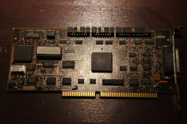
| Compaq | 15MHz ESDI
Controller | 10, 15 |  |
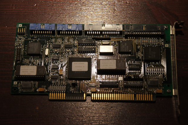
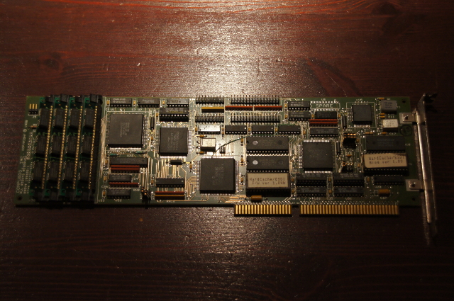
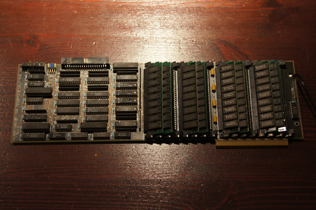
| CompuAdd | HardCache/ESDI
with 4MB Cache | 10, 15 |  |
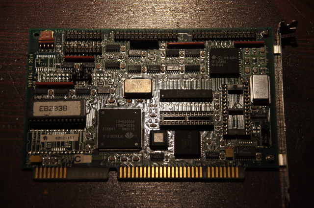
| Data Technology | DTC 6280-15T | 10, 15 |  |
| Data Technology | DTC 6282-15Z | 10, 15 | 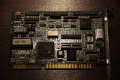 |
| Data Technology | DTC 6282-24 | 10, 15, 20, 22, 24 | 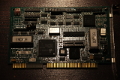 |
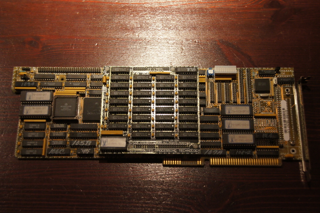
| Distributed Processing
Technology | DPT PM3011E/75
with 4MB
Cache Module | 10, 15, 20 | 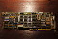 |
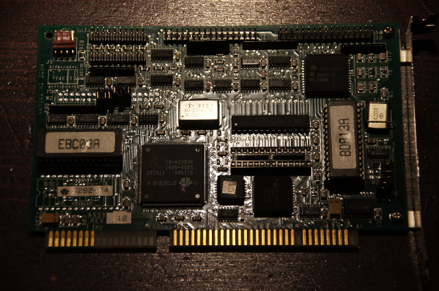
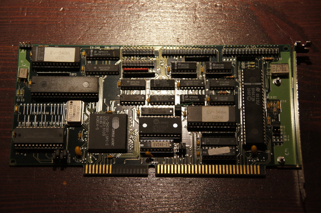
| Everex | EV-348A | 10, 15, 20 | 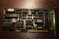 |
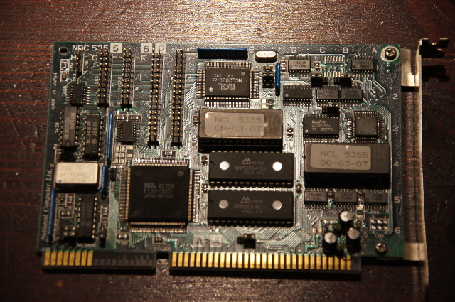
| National Computer
Ltd. | NCL 5355 | 10 | 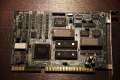 |
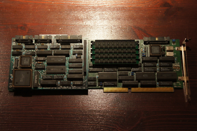
| Perceptive Solutions | hyperSTORE 1600
with
Cache Expansion
Adapter | 10, 15, 20 | 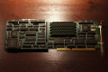
 |
| Scientific Micro
Systems | Omti 8620 | 10 |  |
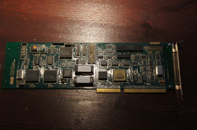
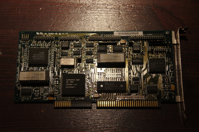
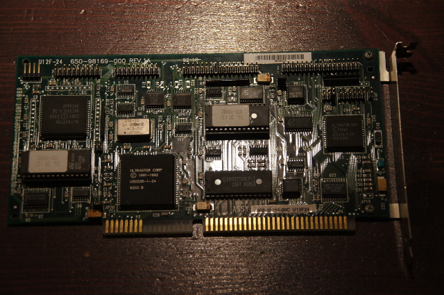
| Ultrastor | Ultra 12F-32 | 10, 15, 20, 22 | 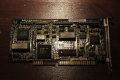 |
| Ultrastor | Ultra 12F-24 | 10, 15, 20, 22, 24 | 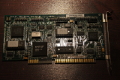 |
| Ultrastor | Ultra 12C with
16MB Cache | 10, 15, 20 | 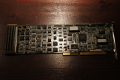 |
| Western Digital | WD1005-WAH | 5, 10 |  |
| Western Digital | WD1007V-SE2 | 10, 15 | 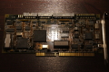 |
| Western Digital | WD1009V-SE2 | 10, 15, 20, 22, 24 | 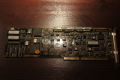 |
... followed by the EISA cards ...
Table 7
Tested EISA ESDI Controller
| Manufacturer | Model | Supported Data
Rates (MHz/s) | Click on Picture
to Magnify |
|---|
| Data Technology | DTC 6290-24
with 4MB Cache | 10, 15, 20, 22, 24 | 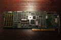 |
| Data Technology | DTC 6295-24
with 2MB Cache | 10, 15, 20, 22, 24 | 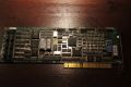 |
| Ultrastor | Ultra 22C
with 0.5MB Cache | 10, 15, 20 |  |
| Ultrastor | Ultra 22CA
with 16MB Cache | 10, 15, 20, 22, 24 | 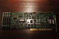 |
| Western Digital | WD1009V-SE2* | 10, 15, 20, 22, 24 | |
* The WD1009V-SE2 - an ISA card - is able
to make use of a Direct Memory Access (DMA) feature in EISA
Systems.
... followed by the MCA cards ...
Table 8
Tested MCA ESDI Controller
| Manufacturer | Model | Supported Data
Rates (MHz/s) | Click on Picture
to Magnify |
|---|
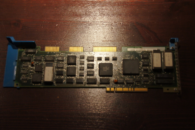
| IBM | IBM ESDI Fixed Disk
Controller | 10 |  |
| Western Digital | WD1007V-MC1 | 10, 15 | 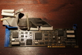 |
... and ended by the bridge controller cards.
Table 9
Tested ESDI to SCSI Bridge Controller
| Manufacturer | Model | Supported Data
Rates (MHz/s) | Click on Picture
to Magnify |
|---|
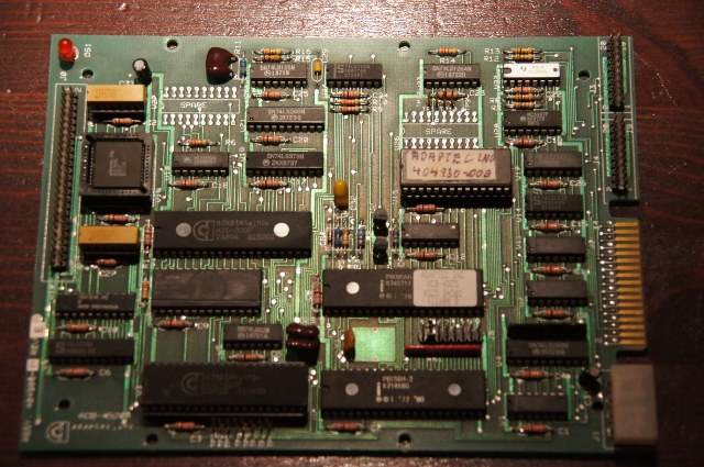
| Adaptec | ACB-4525 S4501 | 10 | 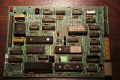 |
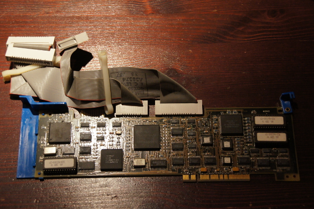
| Emulex | MD21 | 15 | 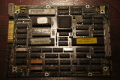 |
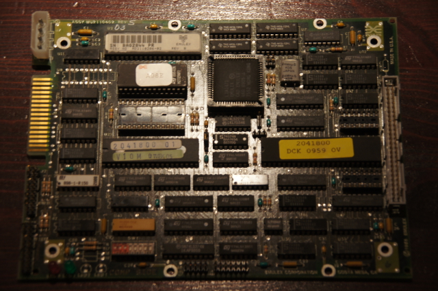
| Scientific Micro
Systems | OMTI 7200 | 10 |  |
General ESDI Controller Features
Early controller cards like the WD1005-WAH couldn't process the data
of one formatted track during one revolution of the drive platter. They
lacked a sufficient data buffer or the buffer was to slow. If a track
can be read during one platter revolution, the sectors of this track are
numbered in ascending order. (Otherwise the sectors are numbered in
interleaved order.) This technology is called one-by-one
interleave. A one-by-one interleave is a prerequisite to achieve a high
data throughput.
Later controller models got a track cache, which allowed the controller
to read ahead an additional track and to store the data in a hardware cache.
Now the track data was stored in SRAM or VRAM ICs, which allowed data access
in the nanosecond range and data throughput only limited by the system bus
bandwidth.
Another feature of ESDI controller cards is the ability to
circumvent limitations of the IBM BIOS for hard disk storage space
addressing. The early IBM BIOSs use a table of fixed drive types, all of
them with 17 sectors per track. Except for the very few 5MHz models, ESDI
hard disks have at least 34 sectors per track. Using an IBM BIOS drive
type for such a disk would mean to waste half of the valuable storage
space.
Several technologies were developed, to circumvent this dilemma.
Basically they translate the physical drive geometry, which consists
of the number of cylinders (cyl), the number of heads (hd), and the
number of sectors per track, (spt) into a logical drive geometry,
which the computer system as well as the operating system is able to
understand and use. These technologies are:
* 17-sectors-per-track translation mode
* 32-sectors-per-track translation mode
* 63-sectors-per-track translation mode
* universal translating mode
* 1024 cylinder truncation
* drive splitting
* track mapping mode
For testing purpose we can narrow down to the 63-sectors-per-track
translation mode and the track mapping mode. The 63-sectors-per-track
mode translates any physical drive geometry into a logical
drive geometry up to 1024cyl, 16hd, and 63spt, thus achieving a storage
space maximum of 528MB. If the drive has more than 528MB storage space -
which is very common for ESDI drives - a track mapping scheme is used,
which translates any physical drive geometry into a logical drive geometry
up to 1024cyl, 64hd, and 32/63spt, thus achieving a storage space
maximum of 1.1/2.1GB (gigabyte). Unless the controller card
isn't able to use either, other translation technologies are applied.
ESDI storage offers an advanced defect management. Any magnetic media
contains areas where data can't be read or written reliably. The location
of these defects are recorded at three different positions on the drive;
sector 0 of all tracks of the maximum cylinder (primary or manufacturer
defect list), sector 0 of all tracks of the maximum cylinder minus eight
(secondary or grown defect list), and sector 0 of all tracks of cylinder
4095 (write protected manufacturer defect list). Every of those sectors holds a
record of the corresponding platter surface defects.
The maximum cylinder and the maximum minus eight cylinder can be
overwritten accidentally, if the drive is low level formatted e.g.
with partitioning software like DiskManager or SpeedStor or with disk
utilities like Seagate's sgafmt.exe. Beware: most ESDI controllers
will even refuse to detect the drive if the primary defect list is
deleted.
ESDI controllers can map defective areas into so called spare
sectors. To make use of spare sectors, the user accessible data will be
reduced usually for one sector per track. A spare sector is
consumed in exchange for a sector in a defective area. Now the drive seems to be
error free to the operating system. The tested controllers will not
make use this feature unless it is mandatory for a certain controller card.
It depends on the manufacturer and the model how the controller
cards performs a low-level-format and how it enables or disables
certain features. This will be discussed in the
manufacturer setup section.
General Controller Setup
As mentioned earlier, ESDI storage systems overcome
certain storage space limitations of the IBM compatible PC.
Storage space limits are not always hardware related.
Even if the hardware is able to address
more than 1024 cylinder, the
operating system is probably not. Some 32Bit operating
systems like NetWare 386 or certain Unix systems have less
problems with this barrier. However, DOS actually has.
What this means is, the user has to work with different
setup methods, depending on the operating system he wants
to make use of. Special problems arise, when more than one
operating system should be installed on the hard disk. To
keep things neat and easy, we limit the setup to DOS,
particularly to DOS versions 4.x and above, because DOS 3.x
isn't able to create partitions bigger than 32MB.
There are a few reasons for a DOS test setup. DOS allows
unrestricted access to the hardware. As a single task
single user operating system measurements are less
influenced by other system bus or processor activities.
WD1003 Compatibility
Standard drive controller cards in a PC have to be
compatible with Western Digital's WD1002/WD1003 drive
controller card. For our purpose it's enough to know
that WD1003-compatibility ensures, that your drive
is recognized by the system, if a proper drive type
is chosen in the system BIOS.
All ESDI controller cards mentioned here will work
in WD1003 compatibility mode. Some offer a native enhanced
mode additionally, e.g. all EISA controller cards. To make
use of this enhanced mode usually an operating system
dependent software driver is necessary. Some cards are
able to activate this enhanced mode for the DOS
environment through their own BIOS.
To be recognized by the system at boot time,
the controller cards must be jumpered correctly.
To make things as simply as possible, we assume,
the ESDI controller is the only hard disk controller
card in the system. If there is a default jumper
setting for the card, it exactly reflects this
condition. If not, the controller has to be jumpered
for:
* primary hard disk port address 1F0-1F7
* enable hard disk controller
* IRQ 14 for hard disk access
Configuring the controller for the secondary port
usually will disable it in the 386/486
environment, because system BIOS usually does not
support the second channel.
Sector and Cylinder Skew
The highest possible data throughput from hard disk
platter occurs, when a read/write head process a single
track. In case a file is to large for a single track, parts
of it may be stored on the same cylinder but on a different
platter of the hard drive. The drive electronic has to switch
between the read/write heads. As high capacity drives, ESDI
Hard disks often employ up to 16 read/write heads. Such a
drive is able to process 16 tracks without moving the read/write
assembly. While head switch time is rather short, it's not
possible for the drive to maintain continuous high data transfer
across read/write head boundaries. One main reason for it is
the drive spin. When a head switch occurs, several sectors of
the following track on the same cylinder pass under the read/write head
before it is able to process the data. The head skew reflects
the head switch time and shifts the sector number accordingly.
If a file resides across several cylinders the read/write heads have
to move on the drive platters. A head move lasts much longer
than a head switch. Again a cylinder skew reflects the cylinder-
to-cylinder access time and shifts the sector number accordingly.
Without head or cylinder skew the platters of a drive have to
spin one unnecessary revolution before the drive electronic
is able to process the data of the following track.
ESDI Controller usually support head and cylinder skewing. Since
head switch time and cylinder-to-cylinder access time differ from
drive to drive, the controller has to calculate the best skew factors.
Sometimes the manufacturer provide a DOS utility program which calculate
skew factors (e.g. Adaptec), when the controller BIOS does not.
Early ESDI controller do not calculate the skew factors but rather
demand user input.
General Options
An other important configuration object is the
controller card's BIOS address. The card BIOS provides
hard disk preparation and setup routines and it
may address the hard disk storage space if
the system BIOS has no
extended Int13H functions. Without that function
there is no support for hard drives with more than 504MB
storage space.
The controller should be jumpered for:
* enable BIOS
* BIOS address C800
In some rare circumstances this area may be
used by another ISA adapter card BIOS already.
In that case use an alternate address e.g.
D800. Note the address setting. It will be
of importance later.
There are numerous other configuration settings.
Assuming the ESDI controller is the only floppy
controller in the system (default configuration)
use:
* primary floppy disk address 3F6-3F7
* enable floppy controller
* single speed floppy disk drives
* auto deselect enabled (hard drive LED flashes
only if the drive is accessed by the operating system)
* caching enabled
Other jumper configurable controller options
are discussed in the manufacturer specific setup.
To complete the physical setup you might want to have a look
at the ESDI cabling.
 back to project list
| © 2016 Wolfgang Gehl
 | 
|